After a few setbacks, I'm back to building my 5-axis CNC foam cutter. I discovered that it was more complex than it appeared and that I needed aluminum and plastic parts for the motion control and even for the CNC controller. So I ended up designing the parts myself using my signmaking program for the vectors and Aspire for the 3D toolpaths.
When I had difficulty finding someone local to machine the parts I discovered that, with a little know-how, they can be machined on the "pea shooter". Then I got to thinking; you know, I could use the router to make metal and plastic parts for other people, in addition to my sign business. Here's a business card design for the project...
[ March 26, 2015, 09:34 AM: Message edited by: Wayne Webb ]
Posted by Wayne Webb (Member # 1124) on :
The parts on the left are some of the components I designed for a contraption called an "omega drive". This is made to fit on the 25 series 80/20 aluminum frame of the foamcutting machine. The springs fit on the little 'knobs' on both pieces and will use the "t-slots" of the extrusions for a channel to slide in. This whole unit will do three things; it will transfer power from the stepper motors via a timing belt, the springs will be in constant tension to keep the belt tight, and the wheel configuration will help to minimize 'backlash' from the g-forces when the belt changes directions. The other part, to the right, is a specially designed motor mount for attaching a NEMA 23 stepper motor to the 80/20 extrusion. The cutout sections were meant to reduce weight and minimize G-forces and hopefully help to eliminate any backlash problem...
[ March 26, 2015, 12:23 AM: Message edited by: Wayne Webb ]
Posted by Wayne Webb (Member # 1124) on :
This one was designed for the bottoms of the two Y axis uprights. I found that the best "linear bearings" for this task was skateboard wheels and designed it accordingly..
Welding the inside frame for the Foamcutter's bed. Posted by Wayne Webb (Member # 1124) on :
The frame parts, ready for painting. The 'feet' are adjustable to make sure the bed will be as perfectly level as possible. Posted by Wayne Webb (Member # 1124) on :
One of the two main bearing mounts made of 1/2'' thick aluminum.
...machined on the Shopbot with a plastic prototype used for test-fitting... Posted by Wayne Webb (Member # 1124) on :
I needed some stand-offs of uniform thickness for the linear guide mounts and couldn't seem to find what I needed on Ebay. So I had some .1875 Plexiglas on hand and made them out of that...
...two if the standoffs with a button-head bolt, ready to mount... Posted by Wayne Webb (Member # 1124) on :
Drilling the mounting holes in the guides, made of cold rolled steel... Posted by Wayne Webb (Member # 1124) on :
The contraption I used to make the bevels on the steel guides... Posted by Wayne Webb (Member # 1124) on :
One of the 90 degree bevels Posted by Wayne Webb (Member # 1124) on :
This is the input/output panel of the CNC controller, designed in SignWizard and cut out on the Bot from a piece of .040 sign aluminum. The top two holes are for an on/off switch and a computer power receptacle to snap into. The next two are for fuse holders and the next cluster of four are for a USB port, two ethernet ports and a parallel port. The six at the bottom are for modular audio jacks; great for connecting power to stepper motor cables.
[ March 26, 2015, 01:02 AM: Message edited by: Wayne Webb ]
Posted by Wayne Webb (Member # 1124) on :
The control box, designed for a solar power system, was perfect for my needs. Here I have masked it with a piece of paint mask to cut out the hole for the cooling fan and a rough rectangle to be cut out with a sabre saw for the output panel.
The finished panel installed. The motor cable jacks had to be disassembled and soldered, which I'm not too good at...yet. Posted by Wayne Webb (Member # 1124) on :
[ March 26, 2015, 12:13 AM: Message edited by: Wayne Webb ]
Posted by Wayne Webb (Member # 1124) on :
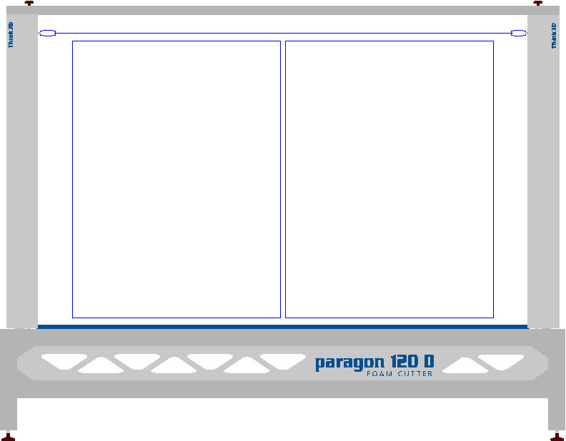
This is a representation of how the foam cutter will look from the loading end. The uprights look wide but this is only an aluminum composite dust cover to hide the motion controls. The horizontal bar at the top can be easily removed for doing taper cuts, if needed, but will probably be left on most of the time. Hopefully, this one will be capable of cutting two 120cf blocks of foam simultaneously. If anyone has a better suggestion for the font I'm open to to that.
[ March 26, 2015, 12:44 PM: Message edited by: Wayne Webb ]
Posted by Dave Sherby (Member # 698) on :
Outstanding work Wayne. How do you hold the foam blocks in place while cutting?
Posted by Wayne Webb (Member # 1124) on :
Thanks Dave, That's a good question. I was thinking only gravity would be sufficient. The bed, 3/4 plywood, will be textured with polyurethane spray-on truck bedliner, then sprayed with DTM acrylic latex. I'm hoping this will provide a little extra grip. Is that going to stick? In addition to that, there will be limit switches installed at both ends of the cutting wire so if the wire ever loses power/heat and tries to catch and pull the foam, it will hit a limit switch first, at either end, and "e-stop" the CNC controller immediately.
[ March 26, 2015, 12:58 PM: Message edited by: Wayne Webb ]
Posted by Ian Stewart-Koster (Member # 3500) on :
Amazingly impressive, Wayne. What are the other two axes past #3 meant to do? Is one rotary, or do you plan to have tilt in X & Y ?
With a photo back near the top you talk about a tensioner for the timing belt. Our router has timing belts on all three axes, and they're tightened by simple 'pull firlmy and then do up the screws tightly' . Backlash and looseness has not been a problem for me, anyhow - not with the confines of the ancient system that it is.
Very Well done!
Posted by Wayne Webb (Member # 1124) on :
Thanks Ian, Yes the 5th axis is to be a rotary "turntable". Both the X and Y have twin motors which will be slaved together for most cutting. For taper cutting, they can move independently.
Posted by Wayne Webb (Member # 1124) on :
Is your timing belt router accurate and fast?
Posted by Wayne Webb (Member # 1124) on :
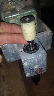
These are my first pressed-on and pressed-in bearings and they are tight. The one on the left is a little too tight actually even though the press put it in there effortlessly. I will have to add about .002 inches to the diameter of the circle in the computer file of the part, then machine another one. Then the bearing will turn freely.
[ March 29, 2015, 01:27 AM: Message edited by: Wayne Webb ]
Posted by Bruce Bowers (Member # 892) on :
I am incredibly impressed with your work.
Posted by David Wright (Member # 111) on :
A lot more interesting than seeing Old Paint redo his bathroom.
Posted by Shirley Carron (Member # 2446) on :
Is that bathroom not done yet?
Posted by Ricardo Davila (Member # 3854) on :
YOU DA MAN, WAYNE !!
RD
Posted by Wayne Webb (Member # 1124) on :
Thanks guys. I'm hoping to have this thing finished soon, so I can make some signs with it.
Posted by Craig Sjoquist (Member # 4684) on :
Impressive
Posted by Wayne Webb (Member # 1124) on :
Thanks Craig.
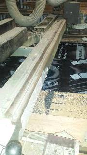
Today, I pulled off the 127'' left side linear rail from the x axis because it just doesn't slide as well as the right one does. I will run my grinding jig over it again to lightly re-machine the 90° v on it's edge and if the axis still doesn't slide smoothly enough, I'll have to make another. But I think it should work.
Posted by Wayne Webb (Member # 1124) on :
The 'decorative; panels are installed, stepper motors, x axis drive systems, trusses installed and welded, 16 leveling feet installed and machine is leveled. Now I have to design a carrier bracket for the drag chain assembly. After the drag chains and tracks are installed, both sides of the x axis will be completed. I have all the parts designed, machined, and ready to assemble on the Y axis except the linear guides. I will make those next. They will carry a light load so will be made of machined aluminum, unlike the steel ones for the x, which had to carry much more. I can finally see the light at the end of the tunnel. Posted by Rusty Bradley (Member # 6938) on :
Wayne has the engineering gene in his DNA to go along with his design and fabrication talents...very impressive.
Posted by Wayne Webb (Member # 1124) on :
Thanks Rusty, I am having a blast building this contraption. It will be even more fun if we make some signs/money with it.
Posted by Wayne Webb (Member # 1124) on :
Got caught up on sign work yesterday afternoon and installed the little v bearings on the y axis "cars". There will be several parts mounted to each of these, including the timing belt, spring/hotwire, the cable drag chain, and a couple of limit switches.
[ June 27, 2015, 10:35 AM: Message edited by: Wayne Webb ]
Posted by Ian Stewart-Koster (Member # 3500) on :
Sorry for not replying sooner, Wayne. Our router began life as an Esab Signmate with 14 ft rails and a pneumatic Z axis in 1989. It was gutted & retrofitted with Tekcel controls and a motorised Z axis in 2001. All servo driven.
I bought it in about 2008, and have replaced 'a few' parts. It's capable of 8" per sec, or 200 mm/sec, but I don't run it at that speed at all - it depends on the capacity of the material, and the geomettry of the cutter.
Accuracy - the software can handle hundredths of a millimetre, but realisticaly the apparently non-existant backlash in the gears would negate a few thou. Its accuracy is fine for all my needs - hardwood, urethane, acrylic, polycarbonate, dibond/ACM, solid aluminium & brass we've engraved and shaped. Aluminium would be my least favourite.
Posted by Wayne Webb (Member # 1124) on :
Thanks Ian. You mention 'gears': Is yours run on rack and pinions or timing belt? If so, what is the size of the belt?
Posted by Ian Stewart-Koster (Member # 3500) on :
Wayne, the X & Y axes have a long rack of about 1" square steel with teeth milled in, bolted to them. There's a gearbox with a gear or cog at the bottom that meshes with the rack, and a strong spring to hold it against the rack. The top end of the gearbox is connected to the servos with a timing belt (toothed)
The Z axis used to have a square thread Acme screw and a delrin (low friction) nut but it gave me terrible problems when doing lithophanes, spo I scrapped it, and put a ballnut & lead screw to suit, in. The top end is a timing gear connected via timing belt with the servo's timing gear.
I've forgotten the designation of the belts, but they're about 1/2" wide or thereabouts, and each tooth is about 1/8", but I can look it up - I bought several spares after one broke one day.
Having the rack gearboxes held againt the rack via a spring, means that if something has to give, for whatever reason, it can. You can push a cam against it, and release it and move the spindle & gantry all over the place for clearance when you want, in a hurry - but you'd need to re-engage it and re-zero or home it afterwards.
As far as aclibration goes, there are something like 647.85 encoder steps per one millimetre of X & Y travel in the driver. I know that's a weird figure, but it is accurate at that setting. When I got it , it was set on about 480 or something where the inaccuracy was not of much consequence milling holes in MDF in small pieces. I went to cut the perimeter of an Alupanel sign that had to be 3035mm long, and it short-changed me and cut it way too short - I managed, but that's when I woke up to the error in the setting.
It's pretty good now for accuracy - a 12 foot panel can be perimeter cut and comes out at exactly 3660mm long with a tapemeasure as well as i can read it.
The Z axis is a different figure - around 400 encoder marks or steps per mm I think - or it could be more - I've forgotten - but the ballnut lead screw has a 5mm pitch, and the timing gears on top have about a 10 to 40 tooth ratio, which is easy to work with, so 4 revs of the servo to 1 rev of the lead screw or 5mm travel.
Posted by Wayne Webb (Member # 1124) on :
Thanks Ian, I was planning to build my next project with servos and rack/pinions too. I had just thought you meant yours was powered only with timing belts and I had never heard of that.
Racks are very strong and plenty accurate enough for what we do. Ball screws are probably the most accurate but they are too pricey for long axes. Short ones like your z are OK.
I guess the timing belt transmissions are used for smooth operation, no?
Posted by Ian Stewart-Koster (Member # 3500) on :
I don't know, Wayne - the timing belt aspect was on it to begin with. It's very practical. There would be pretty high accuracy & no backlash. They're not very stretchable at all.
Posted by Dennis Kiernan (Member # 12202) on :
What are you all talking about?
Posted by Rusty Bradley (Member # 6938) on :
Dennis...I think it's a secret project for the military...Webb Signworks is just a front for the operation.
Posted by Wayne Webb (Member # 1124) on :
I wish... I haven't even succeeded in landing a government sign project above the state level.
Posted by Rusty Bradley (Member # 6938) on :
Wayne...of course...that could blow your cover.
Posted by Dennis Kiernan (Member # 12202) on :
I think Rusty's right. I noticed that plotting was mentioned a couple times.
Posted by Ian Stewart-Koster (Member # 3500) on :
Speaking of plotting...I did make a plotter-blade holder for our router. You can plot through the coversheet of Alupanel etc, then weed it off, scuff and paint. Makes for some decent profits, especially with the 10 x 5 ft sheets.
[ July 01, 2015, 10:08 PM: Message edited by: Ian Stewart-Koster ]
Posted by Rusty Bradley (Member # 6938) on :
Yep...they're speaking in code alright...I don't trust these guys.
Posted by Wayne Webb (Member # 1124) on :
That sounds like a handy invention, Ian. Does it chuck into the router's collet? How do you control the downforce? Compression spring?
Rusty and Ian, We were all geared up for using our code in plotting to sneak our blades and long axes through the weeds with a coversheet but decided to take another route because the timing was wrong and there would be too much backlash.
Posted by Ian Stewart-Koster (Member # 3500) on :
There should be lots of cheap cover cheets with big red crosses full of stars available soon, Wayne...
There are commercial plotter blade holders that go in the chuck, and have a spring-loaded blade for pressure - but I have an aluminium bracket that pokes out the front of the spindle, and that holds the holder when I need it to.
The holder is a bit of 1-1/4" steel rod with a 3/8" hole up the centre, and weights on top, and a Roland blade holder on the bottom. I made a worse looking one before settling on a better one.
It's offset from the spindle centre by about 8mm in Y, and -115mm in X. IN the driver software It is set up[ as a different tool (tool #1) with an offset of -115,8, compared with the spindle which is tool#2 on 0,0.
Alternately you just tell it to do everything with respect to a different origin, which is -115,8 compared with the normally selected & saved origin.
I used to add washers & nuts till I was happy with the weight on the knife. The cnc just lifted it high enough up to clear the substrate by 10mm when travellng to the next pen-down point. I'd set a cutting depth of 1mm, and so the spindle would drop, and the blade would drag, weighted by washers.
The only difference compared with a plotter is you don't get perfect 90 degree corners, as the plotter blade just follows where it is sent, like a caster wheel on a trolley or chair.
I toolpath it as if it's a 1/32" diameter endmill, male/external path and it mildly rounds or radiuses corners, but that is no issue at this scale. (A plotter will overshoot the corner by the blade offset then back up and change direction, for perfectly 90 deg corners etc)
Also you have to set the start & end points of a perimeter path to overlap by 3mm, to be safe. If you do not, then the minute offset of the blade point will give you tiny tags of background that make weeding a nuisance.
Posted by Ian Stewart-Koster (Member # 3500) on :
That's a pen that'll go in the router collet/chuck, but I've done a pen that takes a parker pen refill, and replaces the plotter blade holder - so you can draw big patterns easily - without needing a projector.
Posted by Ian Stewart-Koster (Member # 3500) on :
Here's a thread about making one to work with a stanley knife blade - but mine is nothing like that - way simpler.
I'll try and remember to get some photos tomorrow.
Posted by Wayne Webb (Member # 1124) on :
Thanks Ian
Posted by Ian Stewart-Koster (Member # 3500) on :
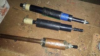
Here are the two plotter blade holders, and a biro refill holder (top):
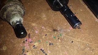
Close-up pic of the tips - with standard Roland 30 degree plotter blades - from Ebay - HongKong.
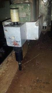
This is the better of the two holders,(the middle one from the top pic) sitting in position in blocks in the aluminium holder in front of the green 3HP Perske router spindle:
This shows me lifting the top up - those are some weights masking-taped together with cream masking tape, and they sit on the slidable blade holder, to provide weight to the blade.
There is about 3/4" of travel up & down in the slider part, so lifting the spindle 1" after every stop, will make sure it clears the substrate by 1/4" as it travels to the next pen-down point. Setting it to 'rout' at 1mm deep means that the entire holder is lower than the travel of the blade holder, so that gravity plus the weights on top do the cutting and the spindle head just steers it.
This shows the gantry - the Y axis. There's about 2 metres in bed capacity width - and the rack is visible on the side. There's a tin box over the servo & gearbox etc at the far end - and you can just see the green Perske spindle at the end, beyond the servo cover.
Hope that helps!
[ July 06, 2015, 03:41 AM: Message edited by: Ian Stewart-Koster ]
Posted by Wayne Webb (Member # 1124) on :
Impressive Wayne Posted by Wayne Webb (Member # 1124) on :
thanks
I have a slight hurdle to get over: When I tried machining just one surface of the 90° "V" on one side of an aluminum flat bar to make one of the two y axis guides, the flat bar warped as crooked as a dog's hind leg. The aluminum built up heat much more easily than expected and that flatbar is totally unusable for a guide now. I was trying to get around using steel, like I did for the x axis, because the Y will be moving and it's weight/mass would increase the g forces on the drive belts causing backlash. But I may have to if I can't find a suitable alternative.
I'll see if I can find some extruded ones but that will mean I will have to re-design and re-fabricate one or two of the parts I've already made. Oh well, I'm this close so there's no need to quit now. Posted by Ian Stewart-Koster (Member # 3500) on :
Wayne, the gantry rolls along the X axis by rolling along some 1-1/4 diameter rod on top of the box section. Under the gantry is a pair of bearings at 12 o'clock and 3 o'clock at the left side, and at 10 and 2 o'clock on the right, I think. There's a back brace on the left also. Gravity does the rest of the work.
The router head and Z axis stuff runs a bit differently. ON the gantry are 2 bits of about 1" or 1-1/8" diam rod going left to right - one on top of the box section and one underneath. The head or Z axis runs on 2 ordinary big sets of bearings against the top rod, and 2 against the underside. They're all mounted in a V orientation, i.e. at 10 and 2 o'clock on top, and 4 & 8 o'clock underneath.
I hope that makes sense!
As for the plotter blade holders - the first one was some domestic copper water pipe, drilled and an ebay plotter blade holder epoxy-glued in the end. That was then attached to another rod that slid up and down with negligible wobble inside another bit of pipe I had in the spare parts heap. The outside was packed up with polypipe to gain the diameter needed to fill the aluminium block that holds it all. So most of the stuff you're looking at is spacers.
The blade itself and the holder have the ability to slide up and down a bit. Stoppers limit the movement. The 2nd plotter blade holder - the black one - has linear bearings in the tube, for the up-and-down part to slide in with no unwanted wobble left or right.
The tube has plastic waterpipe around it to take up the space needed to fill the aluminium holder.
Hope that helps!
Posted by Wayne Webb (Member # 1124) on :
Thanks Ian, I need to make one of those drag knife/pen holders.
Posted by Ian Stewart-Koster (Member # 3500) on :
It's really made the production of painting bigger signs on alupanel etc, very profitable for us - by cutting the plastic cover sheet. You then weed it, scuff it, paint it, and if needed, brush an outline or shade, etc - no vinyl needed, no app tape needed, and very time-efficient, once you have it designed.
Posted by Neil D. Butler (Member # 661) on :
My Head Hurts!
Posted by Wayne Webb (Member # 1124) on :
Sounds very interesting, Ian. How do the carbide blades hold up dragging over that aluminum? Do you use a carbide plotter blade?
I ordered some 'storebought' linear rails from Openbuilds http://openbuildspartstore.com/ They're a little thin and not exactly what I wanted but, they are precision made and maybe they will work if I screw them down good about every 3". They don't have to carry much weight anyhow.
Posted by Ian Stewart-Koster (Member # 3500) on :
Yes, Wayne - 30 degree carbide or carbide tipped blades. They hold up fine - just watch out if the file needs it to run past the edge of the sheet though or you'll break it on the return journey!
I have a fine diamond grit sharpening file (well, a few of them). If I think the cutter blade tip is getting dull, I just put it in the vice, and go over it with the file. That might sound crude, and others might say you're losing the accurate offset measurement, or they're cheaper from china etc etc, but I can get a year or more of life from a blade, with minor touchups like that, and whether your blade offset is 0.25mm or 0.3 or 0.5 or more, in an 8x4 sign seen from 10 feet at the closest, the plotted difference is negligible except in the corners, and I use an offset path with minutely rounded corners anyhow, so the blade easily trails like a caster wheel.
It only takes a minute to freshen the blade - and you can check it with a jeweller's loupe. Never as good as new, but servicable - it is the tip of the point and a smidge ahead of that which does the work anyhow, nor the shiny faces on each side.
The blades do dull quickly if cutting the cover sheet on what we call colourbond steel - and there';s a sign product in that which I used to use a lot, but the aluminium os relatively soft - besides you're not trying to cuit the Al, just cut the cover plastic sheet- that's why there are adjustable weights on the centre top, for pressure variations as required.
[ July 13, 2015, 10:07 PM: Message edited by: Ian Stewart-Koster ]
Posted by Wayne Webb (Member # 1124) on :
I like it very much. I have had good service out of DTM acrylic on PolyMetal and MaxMetal. What kind of paint are you using?
Posted by Ian Stewart-Koster (Member # 3500) on :
various paints: Duraguard low-sheen waterbased UV stable for some black (you might call it latex, but here, latex is junk - we call it acrylic - but it's not acrylic like, lacquer. It's water based house paint. & Enamel - standard stuff & 2-pack urethane for some
Posted by Rusty Bradley (Member # 6938) on :
You know the Supreme Court says you guys can get married now.
Posted by Ian Stewart-Koster (Member # 3500) on :
Sorry, Rusty, I'm having too much fun routing the law...


![[Smile]](smile.gif)


![[Wink]](wink.gif)

![[Cool]](cool.gif)